Sallen and Key filter puzzle with LTspice Leave a comment
Splendidly, there are free Sallen and Key Butterworth filter calculators on the internet now – I used the one on CaculatorEdge – and messing round with them revealed that R1=R2 and C1=2C2 is one recipe for a Butterworth (maximally-flat) filter – straightforward.
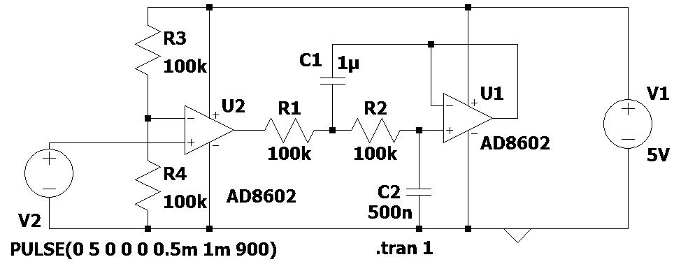
 In order that went into LTspice and I drew out a ~2Hz filter, with a cmos op-amp appearing as a comparator on the front-end to drag the enter of R1 all the best way to each rails (diagram above).
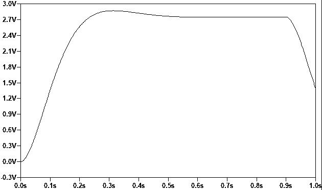
And with a 5V 50/50 sq. wave on the enter, out got here the plot on the left. – not fairly flat, however practically.
The output settles to 2.75V, and with 90% responsibility cycle it settles to a 4.55V, and to 550mV with 10%.
Every appears excessive. Why are these not 2.5V, 4.5V and 500mV? I nonetheless don’t know.
If I put 2.5V dc into R1 (nonetheless in LTspice), the output settles to 2.50V precisely.
The output of the comparator is swinging from 0.0V to five.0V, and in actual life the AD8602 can legitimately be used as a comparator (and the outcomes have been the identical with U2 out of the circuit anyway).
What mistake am I making?